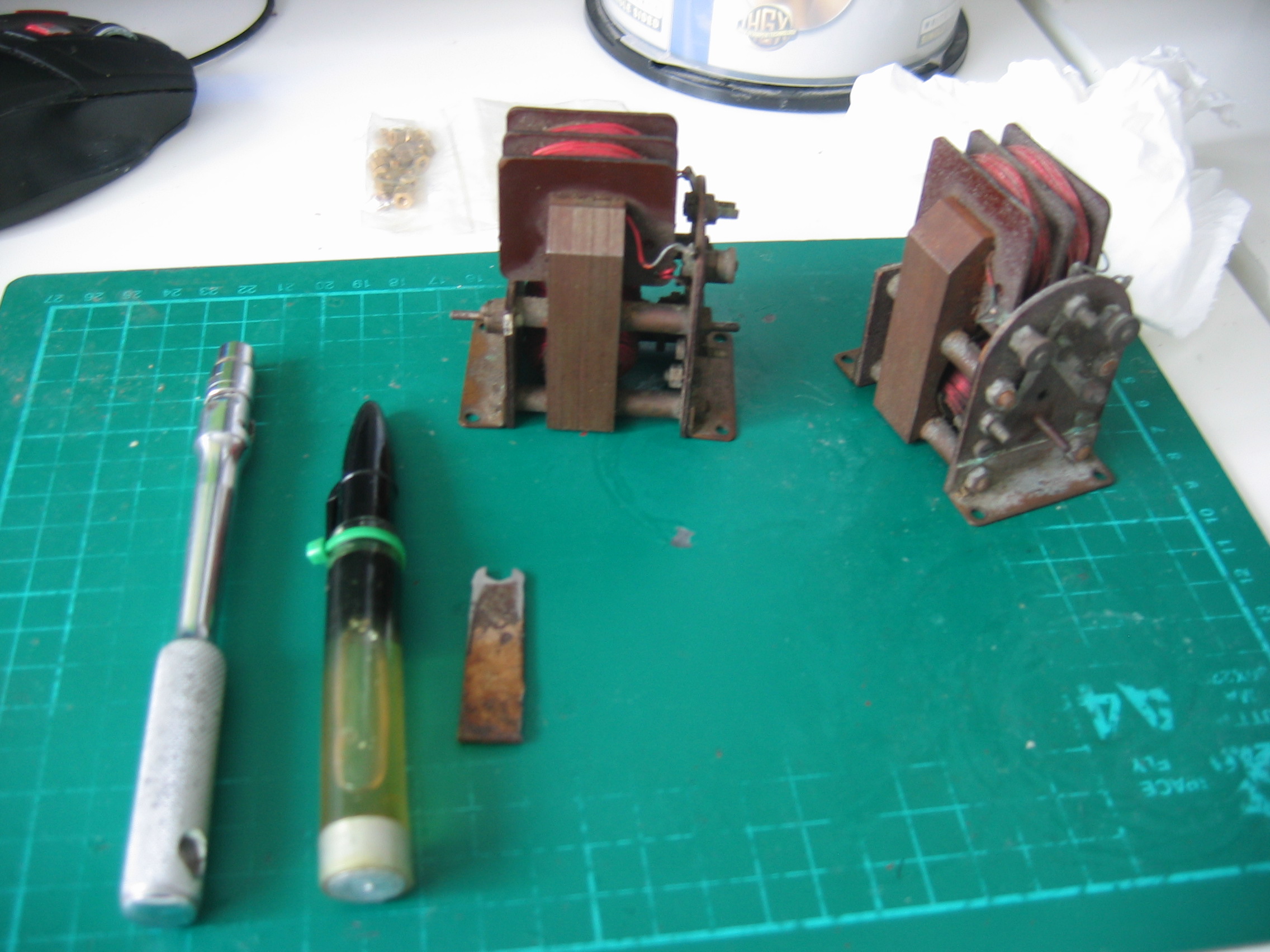
Looking at the pair, they were not badly rusted, though obviously a bit grimey. Oddly, one had strange mount plates - one side being printed on the wrong side and the other claiming that the motor was a Meteor. The wrong side printing was obviously a factory error, but the Meteor mount could indicate that it had been disassembled and reassembled with the incorrect mount.I wonder why?
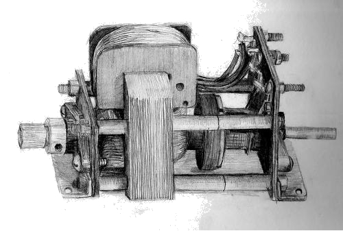
Taycol Model Marine Electric Motors
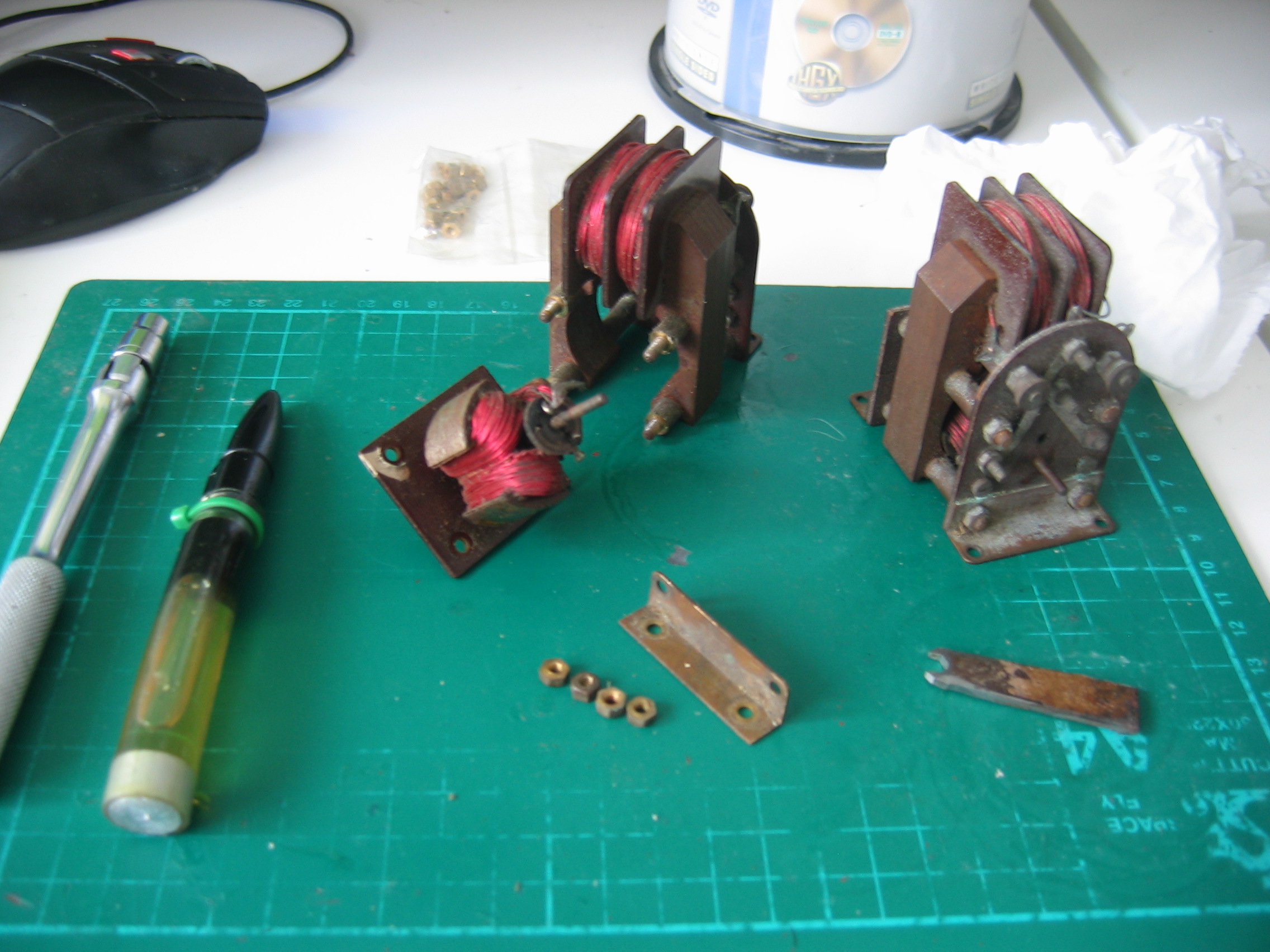
Small Taycol Brush Gear Refurbishment
the motor without brushes has obviously lost the commutator contacts...
One day I had a call from a fellow hobbyist and collector, who had a obtained a couple of Taycol motors in a consignment of Meccano. They looked in worn condition - did I want them?
Well, though Taycols can look old, there usually isn't much wrong with them, and I have always claimed that they can invariably be repaired so I felt that this could be a good opportunity to practice refurbishment, and soon a pair of Torpedoes turned up in my postbox. Grateful thanks to David Dine, who would only take a postage contribution for his trouble... and who has provided the raw material for the pages below...
...while the one that I ran has badly burned brushes,
Here are the commutator plates being 'rough-cut' out of copper shim. As stated above, this is not the right material, but it's what I used for the pictures! See ABOVE for lines and dimensions. Thickness is not really critical here, but the eventual surfaces need to be flat..
The plates are finished off using a small cutting disk in a Minicraft drill. Make sure that the tags are small enough for two to be bent through the hole in the paxolin backing plate without them touching...
...and the final result looks just like new...
Here is a scap of paxolin being spun in a convenient (slow!) drill and brought to round with a cutting disk. If you have a lathe this will be easily done, but I found it perfectly simple to do it this way. Again, the web site provides sizes...
Feeling for the play on the shafts, it was obvious that both motors had had a lot of use. There was the distinct sideways play that owners of old Taycols know causes the worn 'buzzing' sound when they run.
Looking at the commutators, I noted that the 'odd-mount' motor had no brushes, and the surface of the commutator seemed to have lifted off the paxolin. The other motor seemed to be all there, so I oiled the brushes and put 6v across the terminals to see what would happen.
The motor started, but the noise and sparking from the commutator caused me to pull the power after a second. Both motors obviously had been run until the brushgear had worn completely out - probably accelerated by a lack of lubrication which is a trap many Taycol operators fall into.
So, lets look a bit closer...
..and commutator contacts burned completely away in places. Note how the spark erosion has cut away the little tab that holds the contact plate in place. This commutator will soon collapse like the one on the other motor. Now I know why someone took that motor apart...
So let's see how to bring this pair of twins 'back from the grave'. They both need new brushgear. This should be made from .005" phosphor bronze shim - spring temper. Where can you get that?
I found it particularly difficult to source this material. Eileen's Emporium only does 9mm strip - not wide enough for a complete brush, or even the commutator plates. I decided to try making the commutator plates out of copper shim, and make the 'springy' part of the brush out of bronze - soldered to some brass to get the width for the bolt holes.
That was a mistake. The brushes and the commutator plates MUST be made out of the same material to minimise wear. The copper wore through VERY rapidly. And eventually I found a supplier of Phosphor Bronze shim here
Now let's look at the paxolin base of the commutator. Once unsoldered, it simply pulls off the armature shaft. Oh, dear...
The heating from the sparking has destroyed the 1/8" paxolin. So we will need a new paxolin base as well as replacement commutator plates. And brushes...
Here is the 'new' commutator on the right with a tight push-fit central hole. On the left are the remains of the old one.The paxolin just disintegrated once it was unsoldered and the fragments of the plates fell out. I still have to drill the three 'mounting' holes in the new base.
Once that's done the plate lugs are bent to fit in the holes. First they were gently hammered flat, then bent at the lugs and slotted into the holes. A jewelers screwdriver was used to hold the two plates slightly apart while the lugs were bent around at the other side to hold them in place and hammered again. I cheated a bit and used superglue, because I had drilled one hole a bit too wide and the lug kept moving inside it...
Once you have secured the plates, check that there is no electrical connection between them with an ohmmeter. They can be as close as you like, but they MUSTN'T touch...
The completed commutator was then finished off with oiled emery paper to provide a flat contact surface.
And finally the completed plate is pushed back onto the shaft and soldered to the armature wires. Note that the plate join lines are in exact line with the valley between the coils - this is important for the timing. Check that the commutator is perfectly square before soldering as well - it should be resting firmly on the armature spacer all the way around.
That completes the commutator. Now let's look at the brushes. They are a simple bronze strip, with an indentation to provide the actual contact surface. How are we going to do we do that?