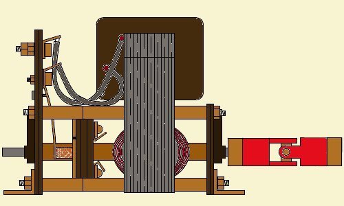
Circuit 1 - for single-coiled Taycols:
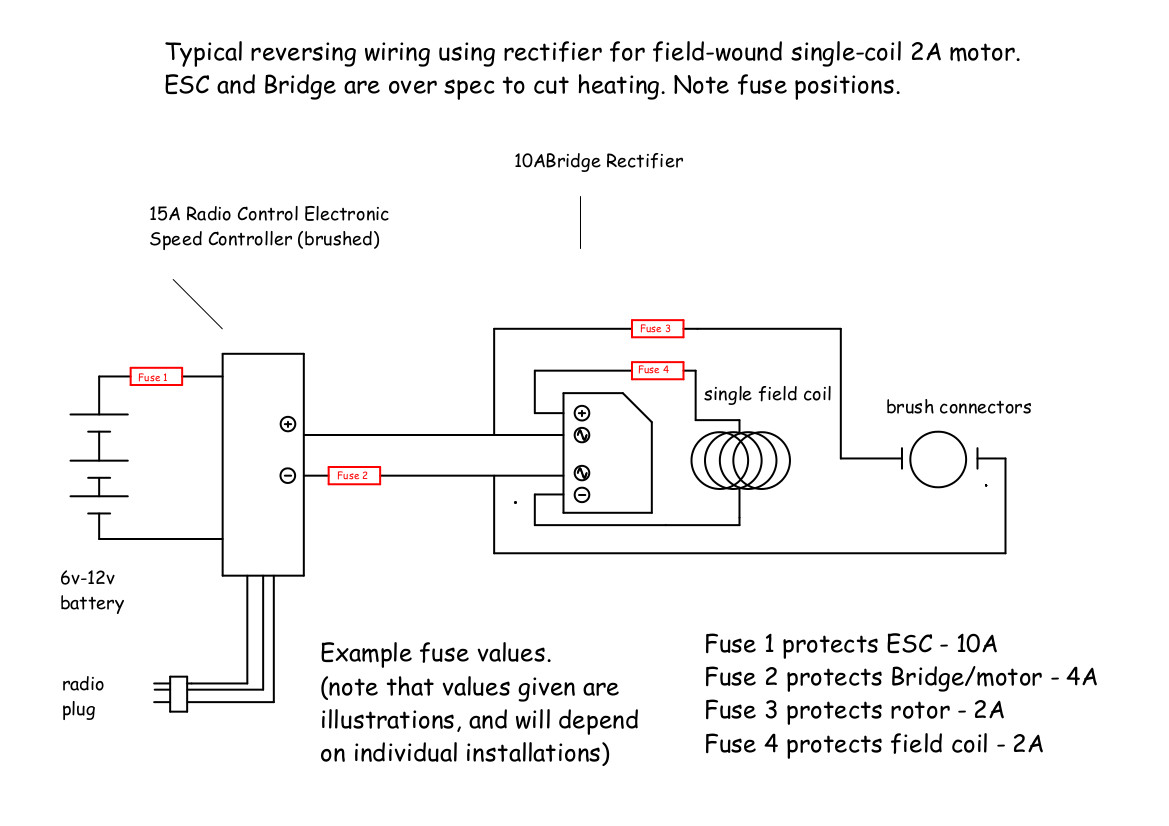
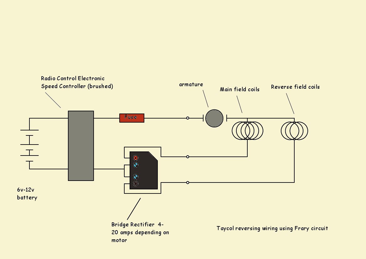
If you feed the field coils through the rectifier while feeding the brushes directly off the speed controller, the rectifier will keep the polarity the same for the field coils when the ESC swaps polarity, and reversing the motor will be possible. The wiring then looks as below. Note that seperating the commutator and the energising coil in this way means that, if the rectifier were to fail, the motor armature might end up with full power passing through it while the external magnetic field was not in operation. This would probably burn out the armature, so fusing the armature line is essential for this circuit. In fact, all lines should be fused, as indicated:
Taycol Model Marine Electric Motors
The Bridge Rectifier circuit above will work for all Taycols, but applying the circuit above to a reverse coil winding Taycol requires the reverse coil connections to be ignored. If your Taycol has a reverse coil winding
you are recommended to use the 'Single Diode' circuit below, which is simpler, and does not need any modifications to be made to the motor...
If you still want to use this circuit with a 'reverse-coil' Taycol, I have included some directions for motor rewiring in the
circuit diagrams for individual motors.
Modern radio systems expect to use an electronic speed controller (ESC) to operate the motor, and this usually reverses the input polarity to make the motor go backwards. As we have seen earlier, this will not work for a field-wound motor.
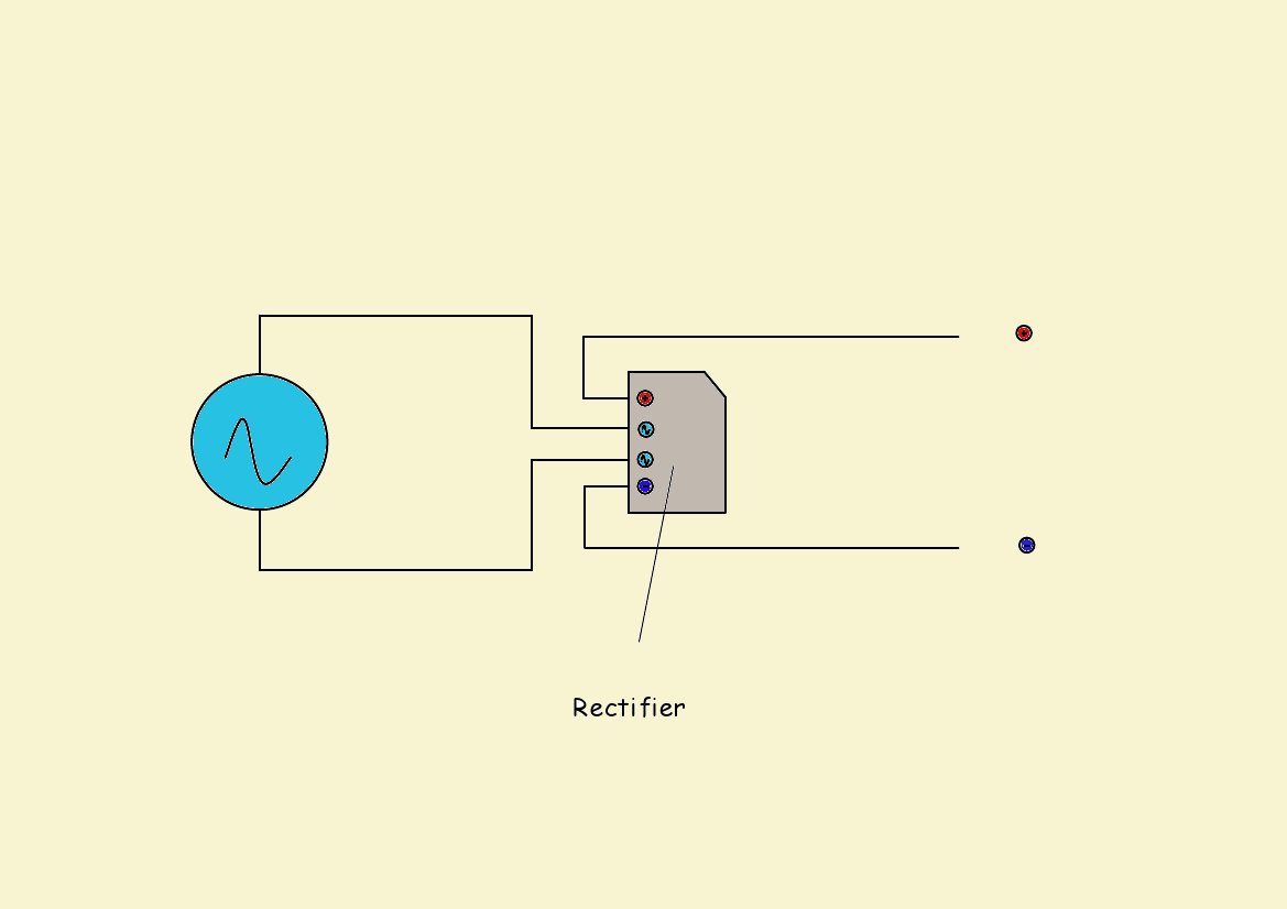
There is a fairly simple electrical work-around for this issue. A bridge rectifier (a fairly common cheap electronic component) may be attached to the Taycol motor in such a way as to allow one set of windings to be polarity-reversed when the speed controller reverses, while leaving the other set at the same polarity. A bridge rectifier is usually used to change AC into DC, where the incoming polarity is switched many times a second, but it will work equally well simply switching the polarity of a single DC line.
The disadvantage of this approach is that a diode rectifier usually lowers the passing voltage slightly, so it will lower the maximum speed available. It also requires some electrical experience to understand what is going on, and some of the circuitry could fail in a damaging way, so adequate fusing is also a must. But if these issues can be accepted, a rectifier is probably the cheapest way to obtain R/C reverse for a Taycol.
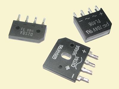
Rectifiers come in several different patterns and sizes, but a common shape looks like the image below left - and the connections are pretty simple...
Which rectifier to get?
For testing, I simply took a rectifier out of an old PC power supply – it turned out to be a GBU4K, which is a '4 Amp Single Phase Glass Passivated Bridge Rectifier 50 to 1000 Volts', and ran all my Taycols under no-load conditions with a 12v battery without problem.
The Taycol motor requirements (see
the leaflet on the site) are typically 2-5 amps, and 10 amp fuses are suggested for the larger motors. The rectifier should be sized for at least the full stalled current of the motor (more is fine), but luckily rectifier costs are not high, and specifying for a high amperage will not cost the earth! So a 10-15 amp rectifier would be needed for the big Taycols, which can be bought on Ebay for a few pounds. Usually a heat-sink is required to let the rectifier run at full design power. At time of writing (2010) I see that Maplins are selling a KBPC2501 rated at 25 amps for a shade over Ł2, which would be more than enough for the biggest Taycol...
Using a Bridge Rectifier for reversing...
Using Single Diodes for reversing...
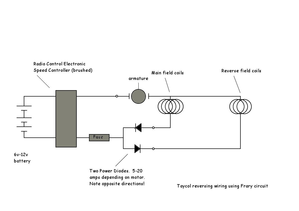
This is a more elegant approach to the problem, provides more authentic engine-room wiring, and uses the Taycol motor in the way it was originally intended. But it can only be used on models with a single-pole reversing coil, and the diodes do lose a bit of power...
Any two diodes can be used so long as each one exceeds the maximum amperage of the motor. And remember that if the diode requires a heatsink then it will not reach its maximum rating without one...
If you have a 'reversing coil' model you can use this simpler circuit suggested by Malcolm Frary of the Blackpool & Fylde MBC.
With two separate single diodes you can wire up BOTH the forward and reversing coils simultaneously, and the opposing diodes will automatically 'switch off' the coil which is not needed. No alteration of the motor wiring is needed at all, but you must be careful to connect the diodes in opposing directions! If you find the motor going backwards when you want it to go forwards, just reverse the diode connections to the coils...
If you have any problems buying single diodes in high amp values, Malcolm points out that a bridge rectifier (which can easily be bought in 25A values for a few pounds) can be wired up to become a diode pair of the kind we want. Simply join the two AC posts together and feed power into this connection - the two other connectors are then led to the forward and reverse motor connectors. The circuit below illustrates this.